SN Engineering · Industrial Electrical Safety & Grounding Solutions +91 9990645119 · www.snengineering.com
Engineered Grounding Solution

Chemical Earthing Electrode System

A professional grounding package combining a project-selected electrode, conductive EBF backfill, inspection access and testable conductor termination.
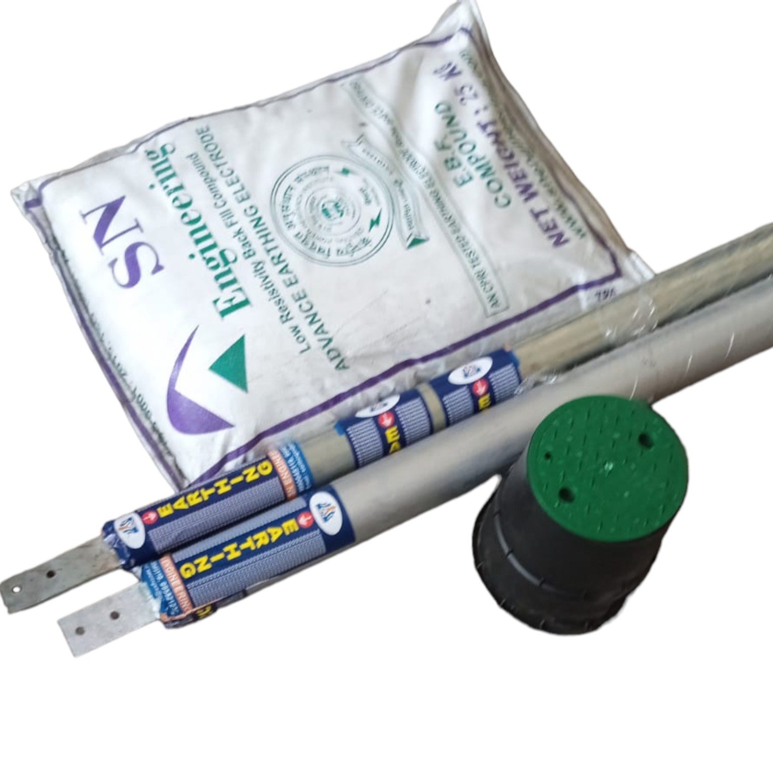
SN Engineering chemical earthing system kit
Electrode · EBF Compound · Inspection Chamber
Project-specific designSelected to suit soil, fault current and project requirements.
Procurement-ready dataStructured for consultants, EPCs, contractors and institutional buyers.
Testable installationAccessible test link and inspection chamber arrangement.
Technical supportSelection, installation and documentation assistance.
System Overview

Designed as a complete grounding system—not a standalone rod.

The final assembly should be selected through approved design data, soil resistivity, project specifications and site conditions.

What the system includes

SN Engineering’s chemical earthing package integrates an electrode, conductive backfill material, connection hardware, an inspection chamber and a testable grounding conductor termination.

Electrode optionsCopper-bonded, copper, GI or project-specified construction.
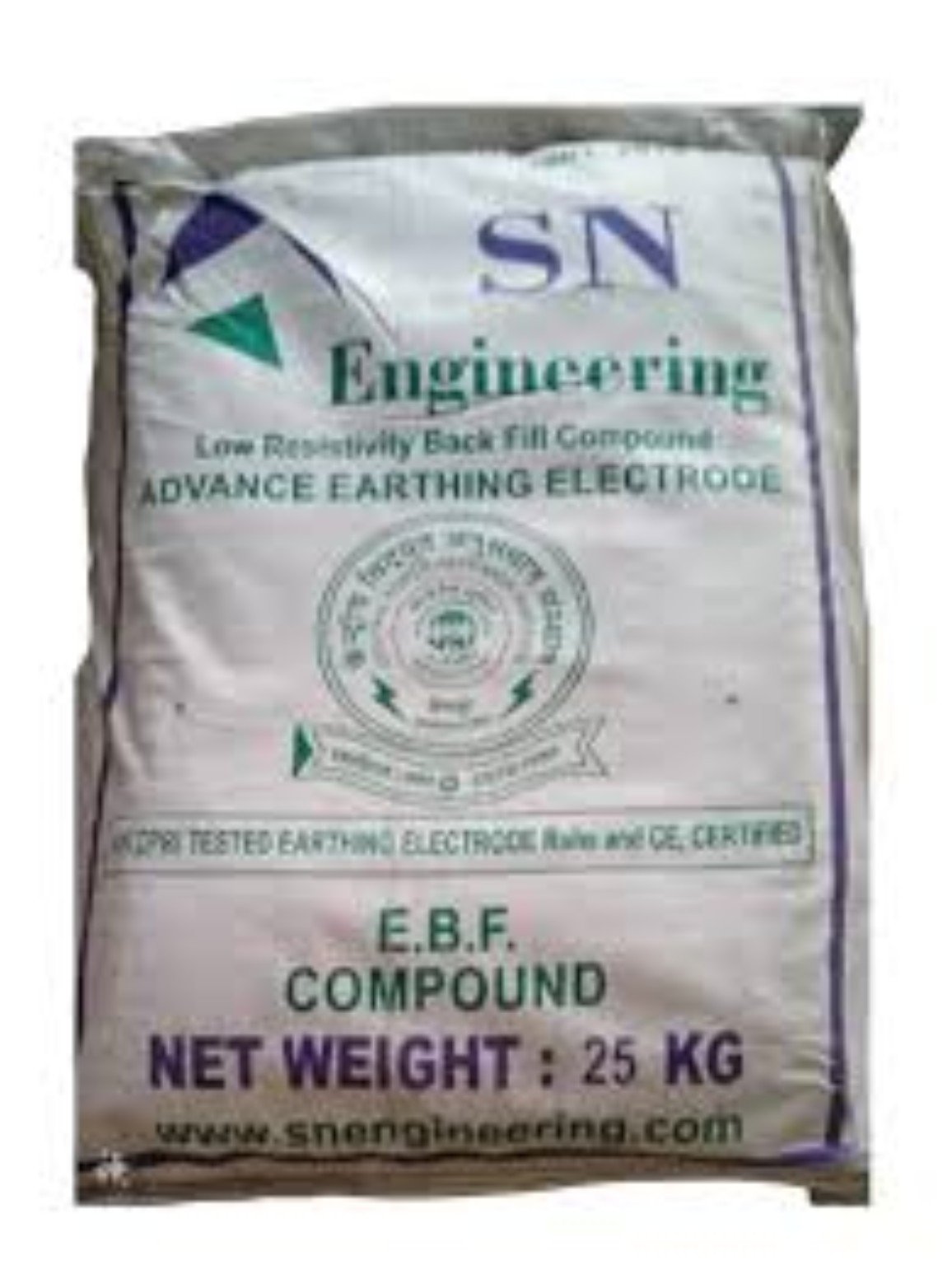
EBF backfillLow-resistivity compound supplied in project-defined quantity.
Connection systemCompatible clamp, test link and conductor termination.
Inspection accessProtected and accessible chamber for testing and maintenance.
Product Presentation

System components and product range

A restrained technical gallery designed for procurement review, product selection and project documentation.

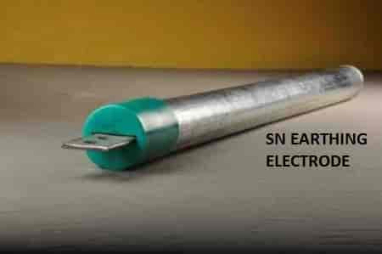
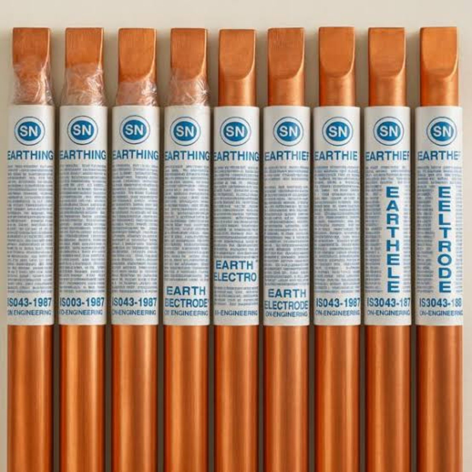
Copper finished electrode range
Copper-finished range

Representative electrode sizes and terminal configurations.

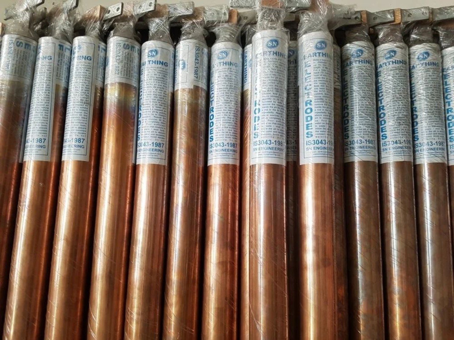
Packed electrodes
Finished product stock

Protective packing and batch-ready supply.

Electrode range
Terminal variations

Illustrative flat, clamp and project-specific terminations.

Specification Framework

Technical data should be project-approved and traceable.

The page avoids invented values. Final dimensions, material, backfill quantity and acceptance resistance must come from approved technical documents.

Engineering selection inputs

Confirm the following before freezing the model:

  • Soil resistivity and site conditions
  • Fault-current and protection study
  • Approved project/tender specification
  • Electrode material and corrosion environment
  • Target resistance and testing method
Electrode constructionCopper-bonded / copper / GI / approved project-specific construction.
Length and diameterAs per selected model and approved design.
Terminal arrangementFlat, clamp, test link or custom project termination.
Backfill compoundCompatible EBF compound; quantity based on bore/pit geometry and approved method.
Connection conductorMaterial and cross-section as per electrical design and fault-current requirement.
Acceptance resistanceAs stated in the approved project specification and applicable authority requirement.
Inspection arrangementAccessible chamber with testable and maintainable connection point.
Procurement Language

Recommended technical specification for government and industrial procurement

“Provide a complete chemical earthing system comprising a project-selected electrode, compatible low-resistivity backfill compound, corrosion-resistant connection hardware, accessible inspection chamber, testable earthing conductor termination, installation, testing and documentation. Electrode dimensions, conductor size, backfill quantity and target resistance shall comply with approved drawings, soil assessment, fault-current study, purchaser’s specification and applicable regulations.”
Claim control: Government, PSU or private-sector names should only be shown against verified tender or project documents. Do not imply approval, endorsement, empanelment or supply history without evidence.
Installation Sequence

Eight-stage installation workflow

Full Installation Guide
01

Site verification

Confirm location, utilities, soil condition and approved layout.

02

Pit / bore preparation

Prepare dimensions as per the approved design and method statement.

03

Electrode placement

Position vertically and protect coatings and terminal surfaces.

04

EBF placement

Place uniformly around the electrode without voids or contamination.

05

Conductor connection

Install compatible hardware and secure testable termination.

06

Inspection chamber

Provide protected, labelled and accessible testing point.

07

Electrical testing

Test continuity and earth resistance with calibrated instruments.

08

Documentation

Record as-built details, photos, results and instrument information.

Applications

Built for industrial and infrastructure environments

Industrial plants

Factories, process facilities, utilities and electrical distribution systems.

Commercial infrastructure

Buildings, data centres, telecom, hospitals and institutional facilities.

Renewable and critical power

Solar plants, generators, UPS systems and sensitive equipment installations.

FAQ

Technical questions buyers commonly ask

What resistance value can be guaranteed?

No universal value should be promised without site data and approved design. Acceptance must follow the project specification and test method.

How much EBF compound is required?

Quantity depends on electrode dimensions, bore/pit geometry, soil condition and the approved installation procedure.

Can government tender references be added?

Yes—only after verifying the tender number, issuing organisation, date and relevant clause from an official source.

Who should install the system?

Qualified personnel working under an approved method statement, electrical safety procedure and project inspection plan.

Need model selection or tender support?

Share the soil report, project specification and required installation details.